Voltage transformer knowledge
Release time:
2023-10-16
Source:
Function of 2. voltage transformer
Classification of 3. voltage transformers
4. According to the insulation method, it can be divided into dry type, pouring type, oil immersion type and air type.
5. According to the working principle, it can be divided into: electromagnetic, capacitive and new photoelectric voltage transformers. The electromagnetic type can be divided into: three-phase type and single-phase type; three-phase type can be divided into: three-phase two-column type and two-phase five-column type.
4. voltage transformer structure
Oil-immersed voltage transformers are divided into single-stage and cascade-type single-stage, single-stage can be used for 220kV and below voltage levels, and cascade-type can be used for all voltage levels of 66kV and above.
The single-stage secondary winding is wound on a common iron core, insulation is not graded, and energy conversion is realized by magnetic coupling.
The cascade type consists of a plurality of primary windings with the same number of turns mounted on the same iron core with half the number of windings, arranged from top to bottom, connected between high voltage and ground.
SF6 gas insulated voltage transformer is composed of shell, insulating sleeve, iron core, 1. secondary winding and installation accessories. The primary winding generally adopts pagoda-shaped layer winding and is wound in a graded manner; the secondary winding is a layer winding, which is wound close to the iron core, and the iron core usually adopts single-phase double-column laminated iron core.
SF6 gas insulated voltage transformer can be matched with GIS, can also be used as an independent SF6 gas insulated voltage transformer.
Cast insulation using unsaturated resin and epoxy resin. Casting insulation voltage transformer is usually used for 35kV voltage level, can be made into indoor, outdoor, grounding, grounding and other structures.
For 10kV switchgear, almost all of them are cast.
Capacitor voltage transformer structure, according to the combination of capacitive voltage divider and electromagnetic unit is divided into: sub-mounted and single column two.
The capacitive voltage divider and the electromagnetic unit are installed separately, and the electromagnetic unit is connected to the central sub-terminal of the capacitive voltage divider through an external bushing.
The capacitive voltage divider and the electromagnetic unit are assembled together up and down, and the two are connected inside the product, which is called single-column type.
1. Single-phase wiring is often used in large grounding current systems to judge that the line has no voltage or the same period. Any phase can be connected, but the corresponding phase of bus voltage should be used for another criterion.
2. A voltage transformer connected between two-phase voltages is mainly used for small current grounding system to judge whether the line is voltage-free or synchronous, because the small grounding current system allows single-phase grounding. If only one single-phase grounding voltage transformer is used, if the voltage transformer is just in the grounding phase, the measured voltage to ground of this phase is zero, it is impossible to verify whether the line is voltage-free, and if wrong judgment is made, it may cause non-synchronous closing.
3. V/V wiring is mainly used for bus voltage measurement of small grounding current system. It can complete three-phase voltage measurement as long as two voltage transformers connected to line voltage, thus saving investment. However, this wiring cannot measure the zero sequence voltage of the system.
Star connection and delta connection are the most widely used, and are often used to measure three-phase voltage and zero sequence voltage.
5. The neutral point is equipped with star connection of arc suppression voltage transformer. In the current grounding system, when the single-phase grounding is allowed to continue to run for 2h, the voltage of the non-grounded phase rises to the line voltage, and there is transient overvoltage for intermittent grounding.
This may cause the voltage transformer core saturation, causing ferromagnetic resonance, so that the system produces resonance overvoltage, so in the small current grounding system voltage transformer to consider harmonic elimination problem.
6. Capacitive type or voltage extraction device is adopted for line voltage transformer used for verification of the same period or line without voltage.
1. The following figure shows the wiring schematic diagram of the secondary circuit of the voltage transformer during the main wiring of the typical double bus or single bus section. As can be seen from the figure, the use of two secondary voltage transformers, a group of secondary three-phase connection into a star, a group of open triangle.
2. A group of star-shaped secondary buses are sent to secondary voltage small buses 1(2)WVa, 1(2)WVb, 1(2)WVc and WVN through the relay 1(2)K contacts of the small air switch 1(2)QA and the auxiliary contacts of the voltage transformer isolating switch. The small buses are used by protection devices and measuring equipment.
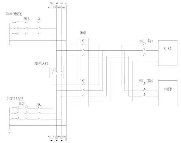
The secondary circuit of pressure transformer parallel is shown in the following figure:

5. Double bus voltage parallel circuit is shown in the figure above. The second parallel condition is that the parallel relays 1QJ and 2QJ can only operate when the bus coupler or sectional circuit breaker is in the closing position and the isolating switches on both sides are also in the closing position.
RELATED INFORMATION
Foshan Shunde District Jingwei Electronic Appliance Co., Ltd.
+86-0757-26623793
4th Floor, Building 5, Meiqi Science and Technology Park, No. 16 Ronggui Avenue South, Shunde District, Foshan City
Copyright©Foshan Shunde Jingwei Electronics Co., Ltd. All Rights Reserved

 中文
中文 English